The Scorpia 220 is my first serious mini quad build. The idea from the start was to build a ZMR 250, but since I got hold of a Scorpia 220 frame and some Cobra motors to go with it the decision was easy. Daniel Tengvall set me up with the frame and the motors. I had a Naze32 lying around since before and the rest of the parts I hunted down from various Internet stores (mostly Banggood).
This is gonna be a somewhat short build log since I didn’t think of documenting it from the beginning. I promise to do better next time 😉
First things first, the parts list:
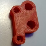
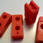
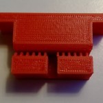
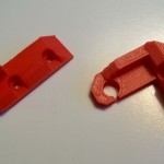
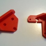
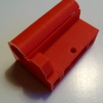
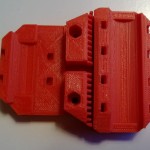
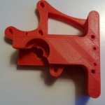
- Scorpia 220 frame (Lizard-rc)
- Purple stand offs (Lizard-rc)
- Purple DAL T5045 bullnose propellers (Birds eye)
- Cobra CM2204 2300kv motors (Cobra)
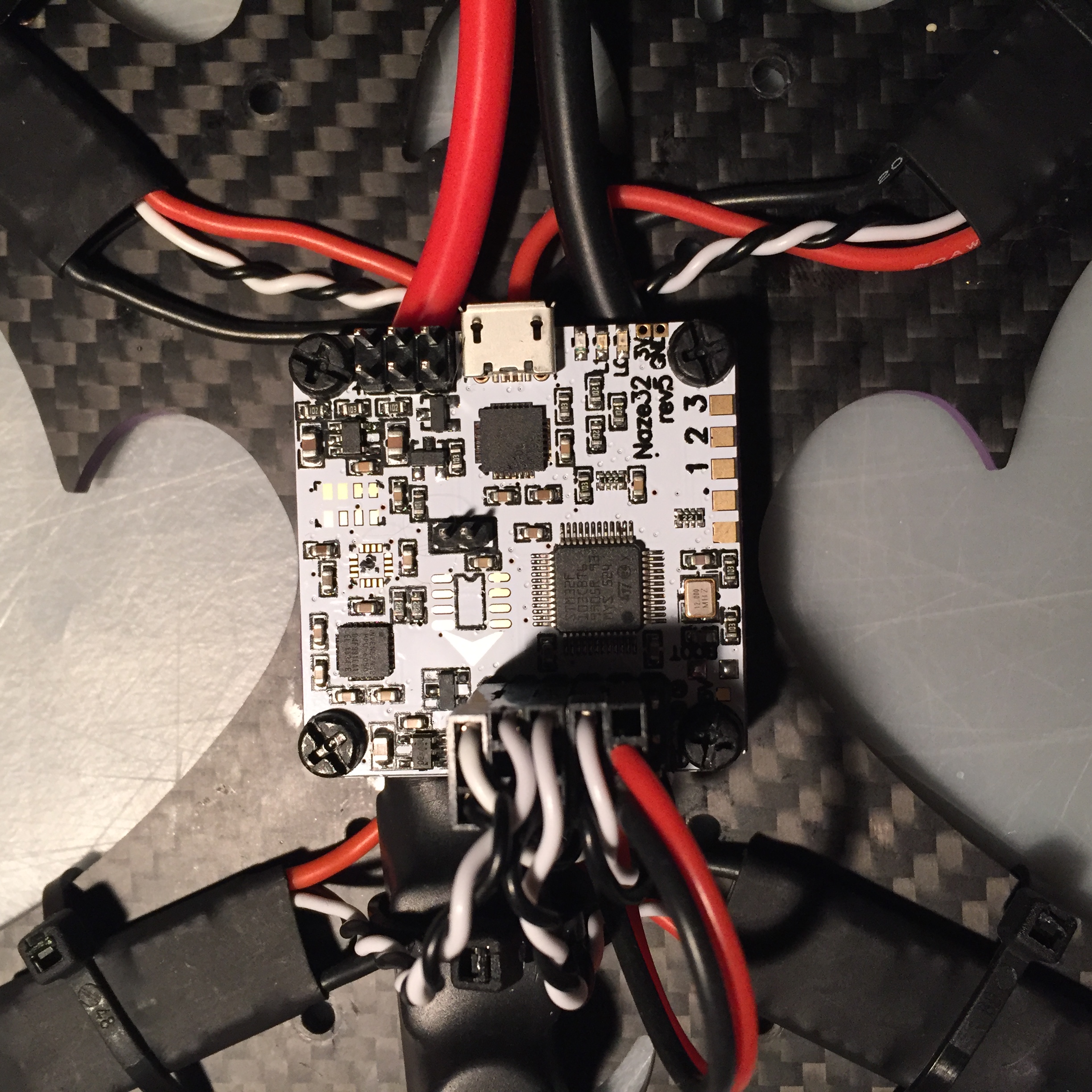
- Afro Naze32 Rev5 DOF6 (eBay)
- CC3D-BEC PDB (Banggood)
- FrSky X4RSB reciever (Banggood)
- LittleBee 20A ESC’s (Banggood)
- Eachine CCD 700tvl/200mW VTX (Banggood)
- Aomway cloverleaf antennas (Banggood)
- 5 cm pigtail for VTX antenna (Banggood)
- 2 – 4S LC filter (Banggood)
- Some cables, connectors and shrinktube
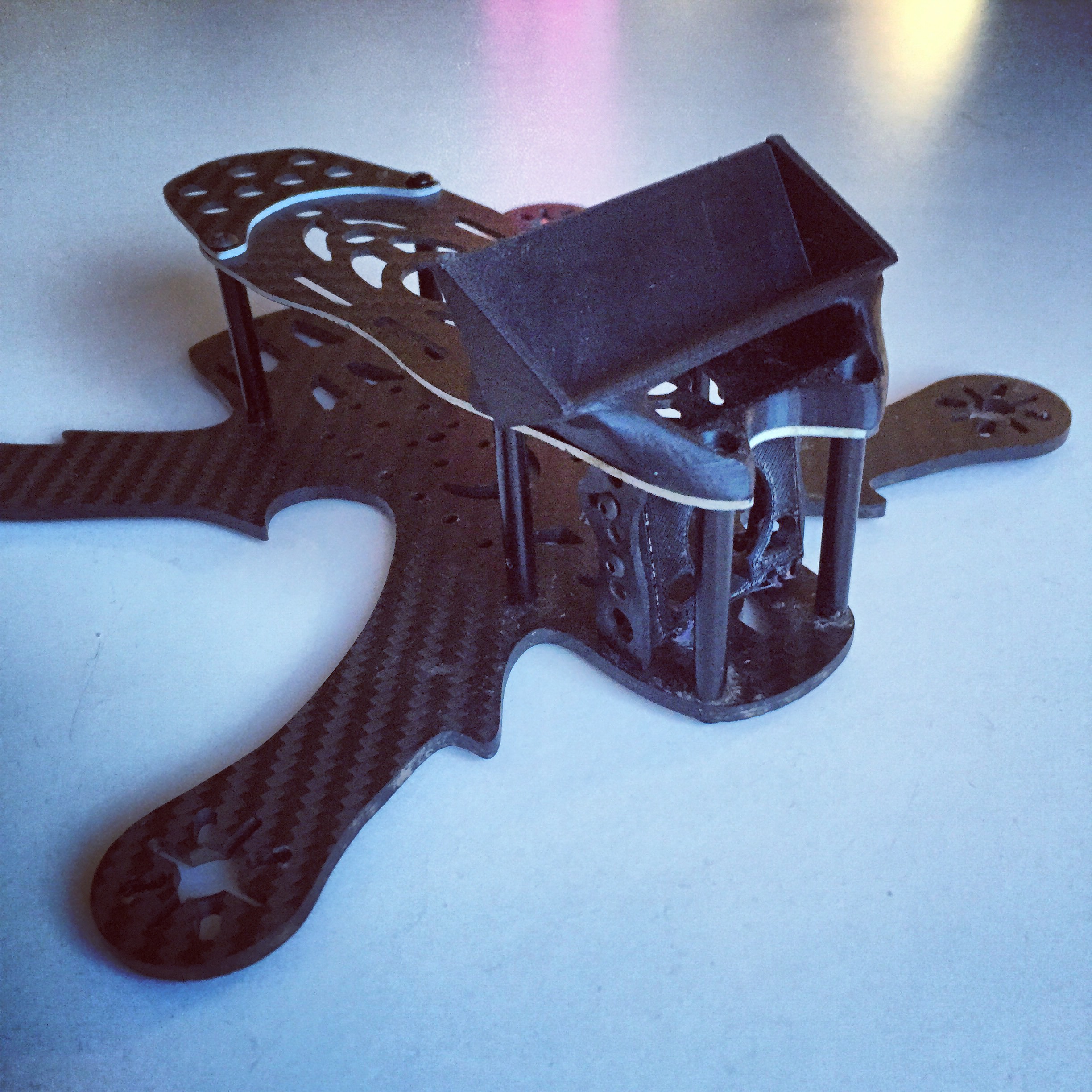
Warpaint
The most important aspect of the build is of course styling your machine 😀 In this case I turned to my daughter and she decided on purple. I use Molotow ONE4ALL markers. They do a great job and don’t need priming before application. Tip; if the surface you’re painting isn’t smooth (for instance the edge of a PCB) take some time to sand it down before painting. The felt tips easily get stuck on rough surfaces.

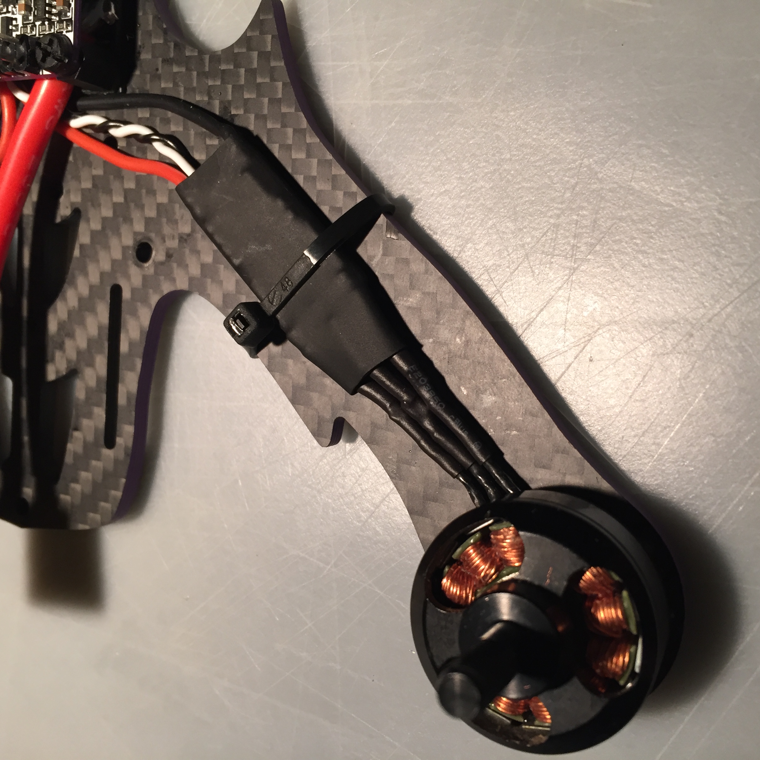
Motors and ESC’s
The motors were previously used so the cables were all different in length and wear-and-tear so I decided to desolder the cables from the ESC’s and solder them to the motors cables instead. Easier to cut them to the preferred length that way. Of course that meant stripping off the shrink tube from the ESC’s and some extra work desoldering and resoldering the cables to the ESC’s. I did think about placing the ESC’s inside the body but ended up leaving them on the arms. Not as pleasing to the eye but hey! I want to get out flying some day soon 😉
Powering up
The CC3D PDB has nice and large pads for soldering the cables from the battery and the ESC’s. The BEC and LED outputs have holes and while that works ok mounting the PDB on spacers it doesn’t work as great mounting it directly on a shim. Note to self; solder any cables to BEC/LED outputs and trim the excess off the back of the PCB before you mount the PDB. The battery connector is a standard XT60 and I used 12AWG silicone cables for connecting it to the PDB (and yes, I’m aware that a switched the black and red).

The PDB has built in BEC’s for 5V and 12V. A comfy feature since the Little Bees are opto ESC’s and lack BEC’s. I’ll power the flight controller and receiver from the 5V but the camera and VTX will be powered directly from the battery through an LC-filter. The quad will be run on a 3S battery initially and going through the BEC on the PDB drops the voltage too much to feel safe.
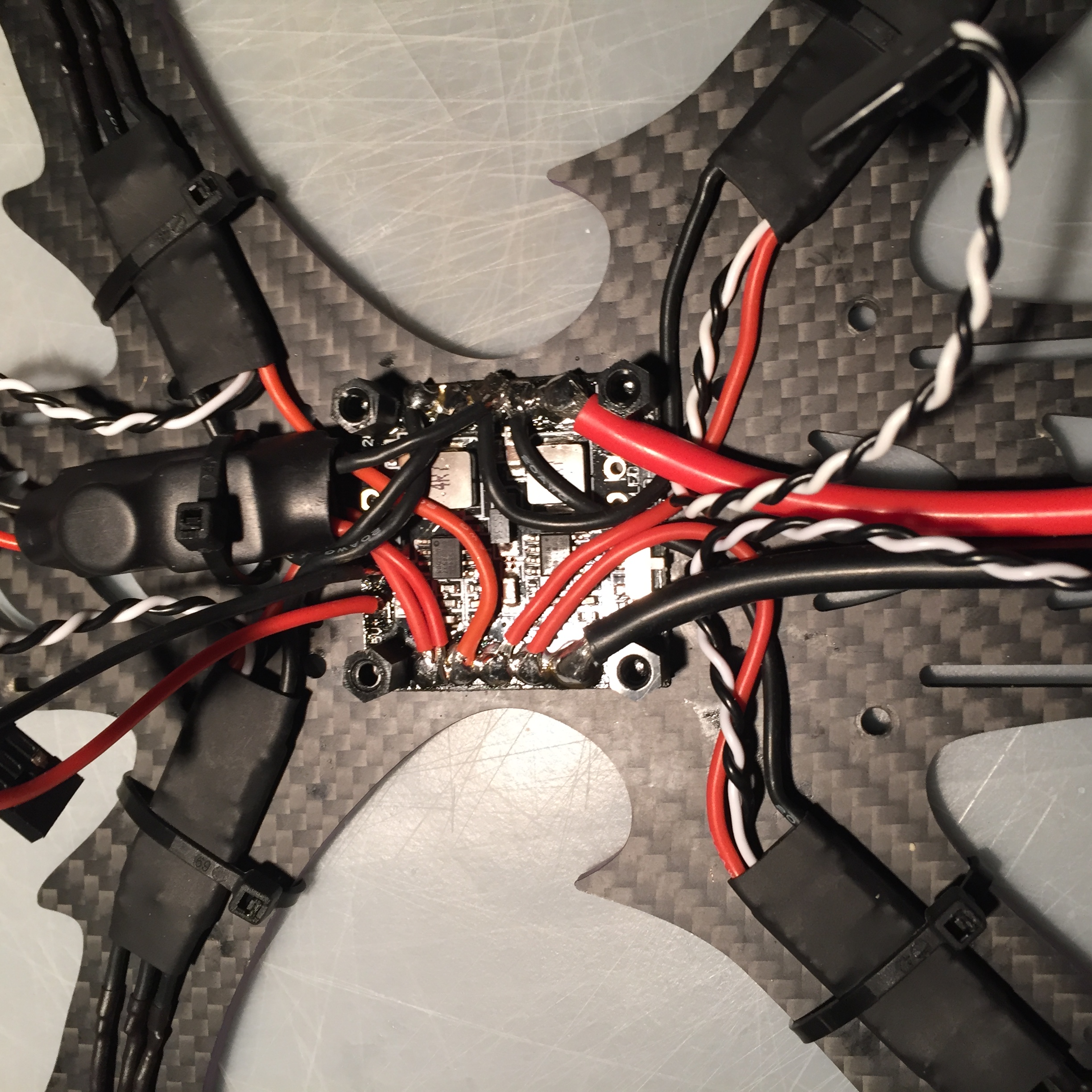
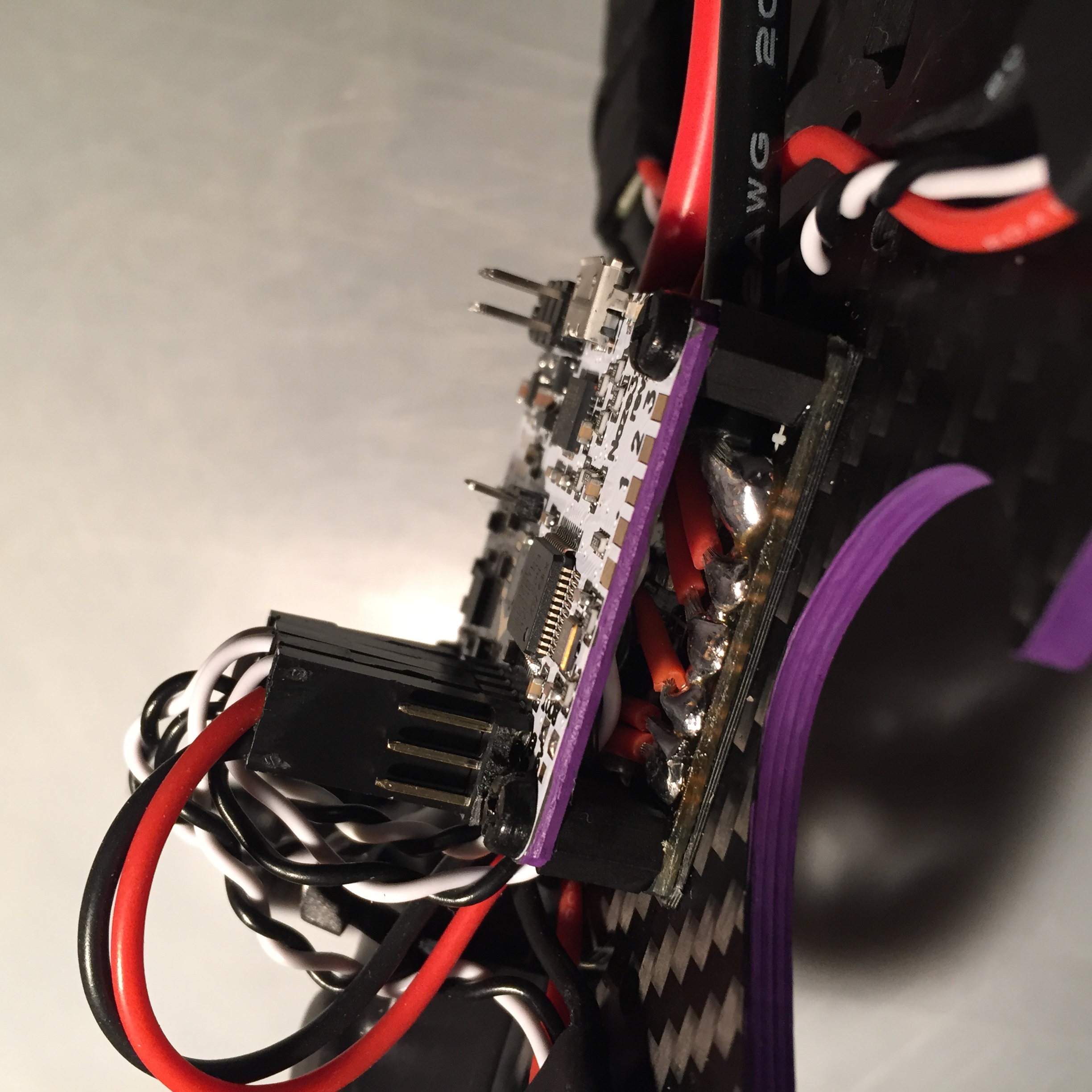
Flight controller
The FC fits nicely on top of the PDB and I was able to tuck away the cables between them for not having any cables sticking out from the sides of the frame. As you can see from the picture I didn’t have any angled pins for the FC but there’s plenty of vertical space in the frame for using straight pins. For the Scorpia Legacy frame I’ll probably solder the control and power leads directly to the FC since it has way less vertical space. The PDB is mounted on top of a .5 mm shim instead of spacers for saving height.
But does it power up?
Time for a test run. Will it smoke or not?
That’s all for now. In the next part I’ll be connecting and mounting the receiver and the camera/VTX and hopefully finish the build. Hope you’ve enjoyed reading and feel free to drop me a line in the comments below.