Don’t drink and commit

I haven’t really done any drunk coding since university (which btw happened waay before git or Arduino saw the light of day ), but gitdown seems just too fun not to try out!

Gitdown uses a BreathShield for Arduino and a Ruby script git hook for checking your BAC before it allows you to commit (or not). In normal mode you won’t be allowed to commit if your BAC is above 0.05% but where it gets interesting is when you set gitdown to either krunk mode or Ball(m)er mode. In krunk mode you’ll need a BAC level above 0.05% and in Ball(m)er mode you’ll need to land a BAC between 0.13% and 0.15%.

Ballmer peak strip from xkcd.com

In the Ball(m)er and krunk modes gitdown also will mess with your commit message as well as post your achievement to the gitdown blog on tumblr.

gitdown tumblr blog post

Scorpia 220 build log part 1

Scorpia 220 frame

The Scorpia 220 is my first serious mini quad build. The idea from the start was to build a ZMR 250, but since I got hold of a Scorpia 220 frame and some Cobra motors to go with it the decision was easy. Daniel Tengvall set me up with the frame and the motors. I had a Naze32 lying around since before and the rest of the parts I hunted down from various Internet stores (mostly Banggood).

This is gonna be a somewhat short build log since I didn’t think of documenting it from the beginning. I promise to do better next time 😉

First things first, the parts list:

Warpaint

The most important aspect of the build is of course styling your machine 😀 In this case I turned to my daughter and she decided on purple. I use Molotow ONE4ALL markers. They do a great job and don’t need priming before application. Tip; if the surface you’re painting isn’t smooth (for instance the edge of a PCB) take some time to sand it down before painting. The felt tips easily get stuck on rough surfaces.

Scorpia 220 paint job
Warpaint

Motors and ESC’s

The motors were previously used so the cables were all different in length and wear-and-tear so I decided to desolder the cables from the ESC’s and solder them to the motors cables instead. Easier to cut them to the preferred length that way. Of course that meant stripping off the shrink tube from the ESC’s and some extra work desoldering and resoldering the cables to the ESC’s. I did think about placing the ESC’s inside the body but ended up leaving them on the arms. Not as pleasing to the eye but hey! I want to get out flying some day soon 😉

Motor and ESC
Motor and ESC

Powering up

The CC3D PDB has nice and large pads for soldering the cables from the battery and the ESC’s. The BEC and LED outputs have holes and while that works ok mounting the PDB on spacers it doesn’t work as great mounting it directly on a shim. Note to self; solder any cables to BEC/LED outputs and trim the excess off the back of the PCB before you mount the PDB. The battery connector is a standard XT60 and I used 12AWG silicone cables for connecting it to the PDB (and yes, I’m aware that a switched the black and red).

XT60 connector
Red is the new black

The PDB has built in BEC’s for 5V and 12V. A comfy feature since the Little Bees are opto ESC’s and lack BEC’s. I’ll power the flight controller and receiver from the 5V but the camera and VTX will be powered directly from the battery through an LC-filter. The quad will be run on a 3S battery initially and going through the BEC on the PDB drops the voltage too much to feel safe.

CC3D-BEC power distribution board (PDB)

Flight controller

The FC fits nicely on top of the PDB and I was able to tuck away the cables between them for not having any cables sticking out from the sides of the frame. As you can see from the picture I didn’t have any angled pins for the FC but there’s plenty of vertical space in the frame for using straight pins. For the Scorpia Legacy frame I’ll probably solder the control and power leads directly to the FC since it has way less vertical space. The PDB is mounted on top of a .5 mm shim instead of spacers for saving height.

Naze32 flight controller
Flight controller and PDB

But does it power up?

Time for a test run. Will it smoke or not?

That’s all for now. In the next part I’ll be connecting and mounting the receiver and the camera/VTX and hopefully finish the build. Hope you’ve enjoyed reading and feel free to drop me a line in the comments below.

Swedish Drone Cup

Swedish Drone Cup 2016, round 1 line up

Last weekend the first race of the Swedish Drone Cup took place. I didn’t have anything to fly so I helped out with the event instead. Sadly the sun didn’t want to join and while battling rain and wind gusts we anyway managed to pull through a great race day.


32 pilots were registered for the race. Some couldn’t make it but 27 made it to the starting line. The anticipation was high while the pilots got ready for the first round of five. Since SDC is a race for best time consistency was key. In order to make it to the top each pilot needed to pass the finish line in at least three heats. The penalty for not finishing a race is huge.

Some footage from the races. Ends with Daniel’s fastest heat of the day.

Jakob Lantz and Anders Lindström battling out in heat #3

We got to see many great battles, quite a few crashes (but no real carnage 😉 ) and some top notch flying. All in all a great race day! At the end of the day Daniel Tengvall managed to out-fly his competitors in the open class and Johan Lindholm placed first in the sportsman class.

Daniel wasn’t just flying, he was also in charge of the whole event. Next time though he can relax and focus on his flying while the rest of us chase him around the race course.

Results – SDC 2016 round 1
Open Sportsman
Daniel Tengvall Johan Lindblom
Anders Nilsson Jonas Åberg
Anders Lindström Fredrik Holmberg

The next round will be held in Löddeköpinge on May 7.

Read more about the Swedish Drone Cup on http://dronecup.se/.

3D printing – but not hasslefree

It’s been awhile since I finished the Prusa i3 printer and ever since I’ve been struggling with getting consistent prints 🙁 Small prints usually works out well, but when it comes to larger parts, for instance replacement parts for the printer it doesn’t deliver.

MEndel Prusa i3

Last night I tried printing new X axis ends. The idler came out ok, at least sort of, but the motor end fails on the first layer. The list of issues is long:

  • slight warp
  • extracted filament lines don’t connect
  • drop effect on some layers
  • tight corners becomes rounded
  • overhangs fall apart
  • the nozzle hits previous layer when bridging

This is the result of the print from yesterday.

Printed with Repetier and slices with Slic3r. 0.5 mm nozzle, 0.3 mm layer height. 3.0 mm PLA, extruder temp: 185°C, bed temp: 60°C (first layer: 190°C/65°C). I’ve uploaded the gcode to Dropbox if you’d like to take a look.

Got a lot of questions right now…

Prusa i3 pt 2 – the plastics

Prusa i3 plastic parts

The first parts I ordered were the plastics. I found a very nice eBay seller; reprappt, who was kind enough as to answer all of my newbie questions even if those not relating to the parts he was selling.

The full list of plastic parts needed for the i3 can be found on the RepRap wiki. Still being a bit confused over the complete material list I compared the parts I received with the list on the wiki. Still confused but it’s falling into place as the build is progressing. I’m the instructions from reprapuniverse.com. Although my setup differs somewhat the instructions are easy to follow and adapt to my build.

Prusa i3 plastic parts

Warping

A few of the pieces have a slight warp and some need clean up of holes and edges but all in all I’m happy with them.

Warping is a common problem with certain thermoplastics. One of them being ABS which is commonly used with 3D printers. When the printing material cools it shrinks and if the material cools too quickly it leads to warping which in turn creates internal stress or tensions within the printed piece. The most common visible result of warping is corners lifting off the build surface.

In order to battle warping and thus creating better build quality a heated bed can be used for slowing down the cooling of the printed piece.

Warping of printed parts

Warping can be not only ugly but also disastrous for precision parts. In my case it’s the X end idler and motor mount. The warp is obvious but the parts will work fine until I can print out replacements.

Cleaning up

Most of the parts need clean up. Usually the printing material closest to the heat bed tends to bleed some. Use a fine file or sandpaper and be careful, especially with parts like the extruder gears.

Close up of the extruder wheel
Close up of the extruder gears

Also some of the holes will most likely need to be widened. Depending on the size and amount of widening needed either use a round file or a drill. Be extra careful if using a drill. The parts can easily crack if the drill bit gets stuck or angled.

Widening the X end idler with an 8 mm drill.
Widening the X end idler with an 8 mm drill

My parts

These are all the plastic parts I have for my build.

This is the second post in the Mendel Prusa i3 printer build log. You can find all posts in the series here.

Building a Les Paul

The Les Paul has been my fave axe for as long as I can remember. Not seeing any falling into my price range anytime soon I’ve been set for a long time on building one.

I do find my way through a workshop but I’m by no means a luthier (yeah, I had to look that up) so I thought I’d pick up a kit with all the critical steps already done. Also since this will be first attempt on “building” a guitar I didn’t want to spend too much cash.

Les Paul kitI finally settled for a 59 model Les paul style flamed top kit off eBay. It’s a set-neck construction, has a basswood body with a flamed maple top and a hard maple neck with a rosewood fingerboard (628 mm/24.75″, 22 frets). Mechanics, pick-ups etc I’ll have to get to later on.

First thing I started thinking about was the paint work of course. Crazy or classic? Crazy will look – just crazy. Classic on the other hand will look awesome, as long as I manage to pull it off.

Seeing I have the 3D printer to work on during summer it will be some time before I come back to this project, but I was too stoked as for not sharing this 😀

Yes, I’m a complete newb and I will make mistakes. But most of all I will appreciate every little bit of advice I can get on the way.

Hooked on 3D

Medel Prusa i3 single frame (photo by Bitfluser @ reprap.org/wiki)

I’ve been browsing around, drooling for a 3D printer for quite some time now but not really having had the budget for one combined with the print quality (or lack thereof) of earlier home/DIY 3D printers I haven’t gotten around getting one. Until now, that is.

After a lot of browsing the Intertubes for information I settled for a Prusa i3 printer. I3 stands for iteration 3 and it’s the latest design by RepRap core developer Prusajr (Jozef Prusa). It incorporates lessons learned from the earlier two models combined with those of other modern RepRap designs.

Medel Prusa i3 single frame (photo by Bitfluser @ reprap.org/wiki)
Medel Prusa i3 single frame model (photo by Bitflusher @ reprap.org/wiki)

Apart form the single frame model there is also a box style frame. While the single frame model requires CNC or laser cutting for milling the pieces the box style frame is designed for easy manufacturing at home from plywood or MDF.

I decided early on that I wanted to get either a kit or buy parts and assemble the unit myself. Partly because shipping would be a pain in the a** and partly because I would probably get hit by additional costs for customs and taxes.

Sourcing the parts from different suppliers proved to be somewhat difficult. Not having a complete shopping list I opted for a few sets of parts; frame kit, plastics and electronics being the main three. In addition I will need a hot end and probably some other bits and pieces on the way.

This is the first in a series of posts about assembling a Mendel Prusa i3 printer.

irisRemote 1.0

Remote control for a Panasonic HMC-41 video camera.

This was a commission project for a friend. I hadn’t been playing with electronics for quite a while before taking on this project. Even had to get a new soldering iron since my old one just didn’t want to fire up. And the multi meter also had seen better days – constantly off by 200 ohms (though accurate enough for the build).

The design is based on an HMC-150 DIY remote controller build by Chris Woodhouse. I didn’t do any major changes except for the cable. Chris originally used an Ethernet cable which he soldered permanently to his controller. I opted for a detachable VGA cable instead.

The major thing I learned from the process was plan ahead. I had to redo the soldering a couple of times due to bad planning. Also make sure your components works visually the way you want. In my case the knobs didn’t cover the nuts of the pots – not looking as good as I planned.

Another thing I probably would have done differently was the control layout. I followed Chris’ vertical layout with alternating positions of switches and knobs. I retrospect the controller would be more ergonomical with a horizontal layout with knobs on top and switches below.

Goodie boxSlaughtered VGA cableCable crimped and sleevedCamera connectorsTesting button layoutCutting holes
Pots and switches in placeCable connectorTesting button orientation and label layoutPot knobsKnobs in placeInside view
Label test printsWrong!Front viewSoldering 101Soldering 101 - againSoldering 101 - yet again
Inside doneirisRemote 1.0irisRemote 1.0

irisRemote 1.0, a set on Flickr.

Gunnar Ulvaeus’ Scrapbook

Gunnar Ulvaeus' Scrapbook running on Surface RT.

If you’re visiting Stockholm I recommend a visit to the newly opened Abba The Museum situated at Djurgården.

I had the pleasure to work on one of the apps for the exhibition; Gunnar Ulvaeus’ Scrapbook. Gunnar is Björn’s father and the app is a digitized version of some of the newspaper and magazine clips he kept during the seventies.

Gunnar Ulvaeus' Scrapbook running on Surface RT.

The app runs on Surface RT tablets at the exhibition. As with most projects we were on a tight schedule and the first version only scratches the surface (no pun intended :P) of the possibilities of Windows Store Apps.

After the initial release we’ve gotten some feedback and are now working on some changes  to improve the app. For instance adding a flip view to make it possible to flip pages by swiping. Once we’re done I’ll get back with some examples on some of the design choices we did.

Meanwhile, get over to the museum and enjoy a piece of music history 😀

Arduino and Nokia 5110 Display

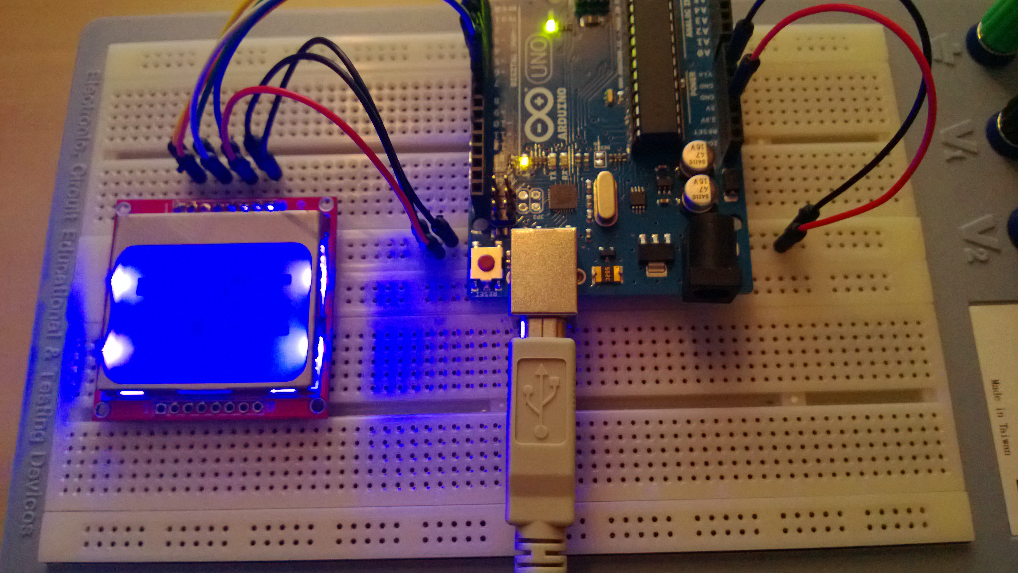
It’s been way too long since I posted something here. Mostly due to a hefty workload and whatever spare time I’ve had has effectively been eaten by other projects. Today finally I got to sit down playing with the Arduino and a Nokia 5110 display I picked up from eBay.

[youtube=http://youtu.be/42lbwEvcPEk]

The libraries needed as well as a tutorial for interacting with the display can be found over at Adafruit. Note that if you don’t use Adafruits version of the display the pin-out might differ.

This is the code for the example above:

[sourcecode language=”C”]

#include <Adafruit_GFX.h>
#include <Adafruit_PCD8544.h>

// SCLK, DIN, D_C, CS, RST
Adafruit_PCD8544 display = Adafruit_PCD8544(7, 6, 5, 4, 3);

#define _W 30
#define _SIZE 4
#define _BASEX 85
#define _BASEY 5
#define _NUMOFCHARS 14
#define _SPEED 2

void setup(){
Serial.begin(9600);
display.begin();
display.clearDisplay();
display.setContrast(10);
display.display();
}

void loop(){
display.clearDisplay();
display.display();
delay(500);

for (int i = _BASEX; i > -width(_SIZE) * _NUMOFCHARS – width(_SIZE); i = i – _SPEED){
display.clearDisplay();
writeAt(i);
display.display();
delay(10);
}
}

void writeChar(int ch, int sz, int x, int y){
display.drawChar(x, y, ch, 1, 0, sz);
}

int width(int sz){
return sz * 6;
}

void writeAt(int pos){
int sz = _SIZE;
int y = _BASEY;

writeChar(‘A’, sz, 0 * width(sz) + pos, y);
writeChar(‘R’, sz, 1 * width(sz) + pos, y);
writeChar(‘K’, sz, 2 * width(sz) + pos, y);
writeChar(‘A’, sz, 3 * width(sz) + pos, y);
writeChar(‘D’, sz, 4 * width(sz) + pos, y);
writeChar(‘T’, sz, 5 * width(sz) + pos, y);
writeChar(‘O’, sz, 6 * width(sz) + pos, y);
writeChar(‘R’, sz, 7 * width(sz) + pos, y);
writeChar(‘G’, sz, 8 * width(sz) + pos, y);
writeChar(‘E’, sz, 9 * width(sz) + pos, y);
writeChar(‘T’, sz, 10 * width(sz) + pos, y);
writeChar(‘.’, sz, 11 * width(sz) + pos, y);
writeChar(‘S’, sz, 12 * width(sz) + pos, y);
writeChar(‘E’, sz, 13 * width(sz) + pos, y);
}

[/sourcecode]

The important thing is not to forget calling display.display() for sending the commands to the display.

Have fun!